Ultrasonic flow meters GFA 202
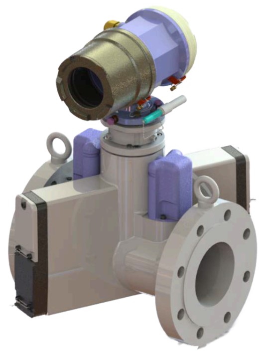
GFA202 — Next-Generation Ultrasonic Gas Meter
The GFA202 is a high-precision, dual-channel ultrasonic gas meter designed to meet the needs of the modern gas industry. The device is intended for measuring the volume and flow rate of natural gas in both forward and reverse directions, ensuring reliable commercial metering even under challenging conditions.
The built-in PTZ volume corrector with integrated pressure and temperature sensors allows accurate conversion of gas volume measurements to standard conditions. The meter operates efficiently on both main gas pipelines and low-pressure gas networks.
GFA202 complies with leading international standards (OIML R137, EN 12405) and has undergone conformity assessment according to Technical Regulations requirements. The device is resistant to environmental influences, operating within a temperature range from –25 °C to +55 °C (up to +70 °C upon request).
Its modern explosion-proof design and intrinsically safe electrical circuit make the GFA202 a reliable solution for companies that require accurate, stable, and energy-efficient gas flow measurement.
Overview: GFA202 — a new generation ultrasonic gas meter
GFA202 is a high-precision four-channel ultrasonic gas meter developed by our startup for the needs of the modern gas industry. The device is designed to measure the volume and flow of natural gas in the forward and reverse directions, ensuring reliable commercial metering even in difficult conditions.
The built-in PTZ volume corrector with pressure and temperature sensors allows you to accurately bring the results of gas volume measurement to standard conditions. The meter works effectively both in main pipelines and in gas condensate field wells, withstanding condensate and humidity in a wide range.
GFA202 complies with leading international standards (OIML R137, EN 12405) and has passed the assessment of compliance with the requirements of Technical Regulations. The device is resistant to environmental influences: temperature from -25 °C to +55 °C (up to +70 °C on request), humidity – up to 100%.
The modern design with explosion protection and intrinsically safe electrical circuit makes the GFA202 a reliable solution for enterprises that require accurate, stable and energy-efficient gas flow measurement.
Main advantages of the GFA202:
– Wide measurement range (Qmin : Qmax = 1:250)
– Built-in PTZ correction with integrated pressure and temperature sensors
– Autonomous operation powered by an internal battery with a service life of more than 5 years
– External power supply (12±3 V DC) — compatible with renewable energy sources (solar panels, wind turbines, etc.)
– Wide selection of outputs for integration into SCADA systems: HF / LF pulses, 4–20 mA, RS 485, discrete signals
– Operating pressure up to 25 MPa
– Nominal diameters from DN 50 to DN 600 (larger sizes available upon request)
– Flange-to-flange distance — 3D, identical to traditional mechanical meters
Additional Features:
Meters can be supplied with calibrated straight sections and flow conditioners. We also design and deliver complete gas metering units (metering skids) for a wide range of applications.
GFA202 is a reliable, modern solution for replacing outdated mechanical devices and transitioning to digital gas metering with high accuracy and full integration into modern infrastructures.
TECHNICAL DATA SHEET FOR ULTRASONIC GAS FLOW METER GFA202
| ITEM | DESCRIPTION |
| GENERAL | |
| Meter Type | Dual-channel ultrasonic gas meter with optional built-in volume correction |
| Application | Measurement of natural gas flow (including commercial metering) |
| Flow direction | Unidirectional; bidirectional |
| Nominal diameters of measuring section, mm | 50; 80; 100; 150; 200; 250; 300; 400; 500; 600 (other sizes available on request) |
| Flange-to-flange distance | 3 DN (for 50–250 mm) |
| PROCESS DATA | |
| Medium | Natural gas |
| Flow rate range under operating conditions, m³/h3/h | See technical data sheet (rangeability 1:250) |
| Maximum operating pressure, MPa | 1.6; 2.5; 4.0; 6.3; 10; 16; 25 |
| Minimum flow velocity, m/s | 0.1 |
| Ambient temperature range (°C) | min.:-25; max.: +55; min.:-25; max.: +70 |
| Strength test | Hydraulic or pneumatic test at 1.5 × maximum operating pressure |
| Ex protection marking as per EN ISO 60079-0:2012; EN ISO 60079-11:2012 |
II 2(1)G Ex db ib [ia Ga] IIA T4 Gb |
| Enclosure protection rating | IP67 |
| FLOW METER TECHNICAL FEATURES | |
| Type | Ultrasonic |
| Accuracy | Maximum permissible error ≤ ±1.0% (Class 1) |
| Nominal diameter of ultrasonic section, mm | Corresponds to pipeline diameter |
| Flow range of ultrasonic meter | According to calibrated range |
| Process connection | Flanges PN (EN 1092); ANSI (ASME B16.5) |
| PPressure and temperature measurement | Built-in (optional) |
| Ultrasonic meter body material | Aluminum (DN 50–150; pressure 20 bar); Carbon steel (other sizes) |
| Ultrasonic meter installation | Integrated with electronic unit |
| Straight pipe section | See technical data sheet |
| TRANSDUCER (SENSOR) | |
| Number of transducers/channels | 2 pairs/ 2 channels |
| Transducer type | Piezoelectric, 200 kHz |
| Signal outputs | 2 × LF / HF pulse outputs, 2 × NO 24 V DC 50 mA discrete outputs, 1 × RS 485 (Modbus RTU), 1 × 4–20 mA analog output; OR: 2 × LF / HF pulse outputs, 2 × NO 24 V DC 50 mA discrete outputs, 2 × RS 485 (Modbus RTU) |
| Power supply | (12±3) V DC external power supply; optionally built-in battery (autonomous operation ≥ 5 years) |